|
|
I/O-SIM is a comfortable tool for commissioning of any MPS® Station. You need following I/O data cable ( order no. 034 031)
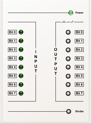
You can set output signals and view the sensor signals of a connected MPS® Station.
Switch – Strobe
The strobe switch enables the switches Bit 0 to Bit 7. To generate output signals via the switches Bit 0 to Bit 7, the strobe switch must be set left. You have to push the strobe switch to the right side if you want to send a signal pattern set by the switches Bit 0 to Bit 7 at well defined time slots.
Switches – Bit 0 to Bit 7
Using these switches you can set output signals or you can generate a bit pattern depending on the position of the strobe switch.
LEDs – Bit 0 to Bit 7
The LEDs show the status of sensors of connected MPS® Station.