|
|
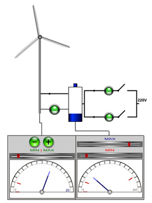
The process model consists of the following components:
- Generator: Adjustable power loss; the power is regulated at random or by clicking on the “green” +/- button with the mouse.
- Accumulator with adjustable minimum and maximum charge state
- Two lamps with differing wattage
- 230 V voltage
- Two controllable switches
The task is to control the switches so that the loads (lamps) are always supplied optimally but so that overcharging and undercharging of the accumulator are avoided. The limit values can be varied constantly with the mouse on the indicators (generator power resp. accumulator charge level).
- 1 sensor for detecting whether the generator is generating power, 1 sensor in each case for detecting whether the charge state is above minimum or maximum level.
- 1 actuator for connection of the generator to the accumulator.
- 2 actuators for connection of the first lamp resp. the second lamp to the accumulator.
- 2 actuators for connection of the first lamp resp. the second lamp to the power supply network.